How to do a spin coating PDMS membrane?
_ Application Note
A thin layer of PDMS is called a PDMS membrane. The PDMS membrane is used in a wide range of application due to its several advantages.
Because the PDMS is permeable, the PDMS membrane can be used to exchange gas (in cell culture application for example) or small molecule (in filtration application). What’s more, because the PDMS is soft, a membrane can be used to create valves such as Quake valves.
The PDMS membrane utility is not limited as before, depending on the thickness the diffusion and the softness of the layer will be adjustable to a lot of application. We are going to see here how to make a PDMS membrane and manipulate it. The PDMS membrane can be done with few equipment that you can find in our PDMS membrane station.
How to fabricate a PDMS membrane in 4 steps
- Pre-preparation steps (mainly cleaning)
- Creation of a sacrificial layer
- Creation of the PDMS layer
- Release of the PDMS membrane
1. PDMS membrane : Pre-preparation steps
The PDMS membrane is generally done by spin coating and so using a wafer as a substrate. Before to use the wafer, it has to be cleaned. A classic cleaning is recommended as described here.
If you are in a clean room, you can clean it with piranha solution (H2SO4+H2O2), outside a clean room you can use acetone. The cleaning can be optional if you are sure about the state of your wafer but strongly advised. In any case you have to heat your wafer to remove all moisture on the surface. We advice 15min at 120°C on a hot plate for example. If needed, a plasma treatment during 2 minutes will increase the wettability of the surface and so the spreading on your wafer during the spin coating.

2. PDMS membrane : Creation of a sacrificial layer
To be able to remove the PDMS from the substrate, the best way is to use a sacrificial layer that will be removed at the end of the process to release the PDMS.
You can use several materials for the sacrificial layer, we use some AZ4562 photoresist because it is easy to handle and works perfectly.
To create the AZ4562, spin coat the photoresist (1ml per inch of the substrate), you will obtain a thin and planar layer. Then bake it at 100°C during 2 minutes. There is no need to have a temperature ramp for heating or cooling down, so you can directly remove the wafer from the hot plate after the 2 minutes.
There is no need to expose the photoresist, the wafer is already ready for the next step.

Spin coating parameters:
| Speed | Acceleration | Time | |
| Step 1 | 500 rpm | 300 rpm/s | 10s |
| Step 2 | 5000 rpm | 300 rpm/s | 30s |
3. Creation of the PDMS layer
The PDMS membrane is made by spin coating the PDMS on the substrate, so before that, the PDMS has to be prepared. It means, mixing of the monomer and of the curing agent (10/1) and degassing the PDMS.
The most relevant step is now! The thickness of your future PDMS membrane will depend on the viscosity of your PDMS mix and on the spin coating parameters (the speed, the acceleration, and the time of the spin coating). The parameters of the spin coating can be easy set with your spin coater and will lead to different thickness for a given viscosity of your PDMS mix. Indeed, with time, once you mix the monomer and the curing agent the reticulation begin and with it the viscosity will continuously increase. So according on how long you wait before to do the spin coating step, you will have a different viscosity and so a different thickness for the same spin coating parameteres.
These seems tricky but once you have done your tests for different value, the process is really well reproducible and since you can wait for a long time or a really short time, you can achieve really thin PDMS membrane or really thick PDMS membrane.
You will be able to have some information on what kind of layer you might obtain according to the parameters you are using in the following graphic.
 Figure 1: Dependence of PDMS layer thickness for microfluidic devices as a function of spin-coating speed for a 5 min spin-coating time (left) and as a function of spin-coating time for two given spin-coating speeds (right).
PDMS part A and part B (Sylgard 184, Dow Corning) mixed in a 10:1 (weight:weight) ratio and steered during 2 minutes. The PDMS was placed in vacuum desiccators for degassing (10–13 minutes) before use. Total preparation time: 15 minutes. Figure adapted from [1].

Figure 2: PDMS layer thickness as a function of spin-coating speed
Sylgard-184 PDMS used just after base and curing agent were mixed in a 10:1 ratio. Dark blue circles are data points from [3] with a 60s spin-coating time, light blue circles are measurements with a 30s spin-coating time and the solid line is the theoretical fit W=0.23 ω-1.14 (W in meters, ω in rpm).
4. Release of the PDMS membrane
Now you have your membrane at the wanted thickness but it is quite difficult to handle and take it out the wafer, that’s why we used a sacrificial layer.
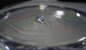
You just have to put the wafer in a acetone solution and wait the dissolution of the AZ4562. It will take few minutes (2-3min), then you will have your PDMS membrane floating on the surface.
Note that the best is to keep the PDMS membrane into water to easily manipulate it since it is really sticky.

Congratulation you have done your PDMS membrane!