The first and most intuitive fabrication method for paper microfluidics designing relies on cutting the paper to obtain the desired shapes and channels.
Fabrication method:
The objective of this method is to define channels within a substrate made of paper by cutting the outline of the desired pattern, using either a blade or a laser. The solvent flow direction is thus controlled by the edges. In order to ease the manipulation of the microfluidic paper-based analytical device (µPAD), several strategies can be adopted:
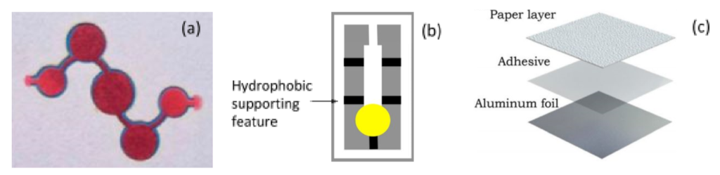
– It is possible not to completely close the inlet and outlet of the device so that it remains attached to the rest of the substrate (Figure. 1.a).
– Some hydrophobic features can be added, linking the channels to the substrate but this entails the use of hydrophobizing agents (Figure 1.b).
– An hydrophobic layer can be attached at the back of the paper, prior to cutting. This layer should not be cut during the process to maintain the device on the substrate. Nie and al. [2] presents the use of an aluminium foil and an adhesive layer for a laser-cutting process. The power of the laser is tuned to be low enough not to cut through the aluminium foil (Figure 1.c).
– Finally, if the device is large enough, it is possible to cut it entirely from the substrate and manipulate it directly.
Figure 1: Three examples of paper-based microfluidic devices with different holding approaches: (a) the structure remains attached at the input/output [2], (b) waxed features are used [3], (c) the paper is fixed with an adhesive layer on an aluminium foil [4].
Upsides/Downsides:
This method is a one-step process that does not require any solvent, making it ideal for a fast prototyping. Cutting machines using a blade can have an acceptable resolution for a low price while laser printers offers a more expensive solution for a greater accuracy, the consumable is then limited to paper which is cheap. Yet, the parameters have to be well adjusted to prevent tearing the paper or leaving burn marks according to the method used.
References:
[1] A. W. Martinez, S. T. Phillips, G. M. Whitesides, and E. Carrilho, “Diagnostics for the Developing World: Microfluidic Paper-Based Analytical Devices,” Analytical Chemistry, vol. 82, no. 1, pp. 3–10, Jan. 2010.
[2] J. Nie, Y. Liang, Y. Zhang, S. Le, D. Li, and S. Zhang, “One-step patterning of hollow microstructures in paper by laser cutting to create microfluidic analytical devices,” The Analyst, vol. 138, no. 2, pp. 671–676, 2013.
[3] A. Rayaprolu, S. K. Srivastava, K. Anand, L. Bhati, A. Asthana, and C. M. Rao, “Fabrication of cost-effective and efficient paper-based device for viscosity measurement,” Analytica Chimica Acta, vol. 1044, pp. 86–92, Dec. 2018
[4] M. A. Mahmud, E. J. M. Blondeel, M. Kaddoura, and B. D. MacDonald, “Creating compact and microscale features in paper-based devices by laser cutting,” The Analyst, vol. 141, no. 23, pp. 6449–6454, 2016.
For further information and quotes, do not hesitate to contact our team of experts: